


Solar PV systems generate electricity using sunlight ( Solar energy ). Solar is a clean source of energy and hence, the generation of electricity from solar does not cause pollution. Solar is the center of attraction when it comes to renewables. The electricity generated from PV systems can either be used directly or it can be stored in a battery and used when required.
Sometimes, PV systems are connected to the national grid, and the electricity generated from PV is fed into the national grid. Such PV systems are known as on-grid PV systems. When PV systems are not tied to the national grid, they are known as off-grid PV systems. In such systems, PV is the sole supplier of electricity. Residential systems mostly use on-grid PV systems. The residential PV systems must be designed according to the power requirements and location of the installation. Several factors like location and weather are taken into consideration while designing a PV system. Each component of a PV system requires a specific design. This article discusses the design of each of the components in detail.
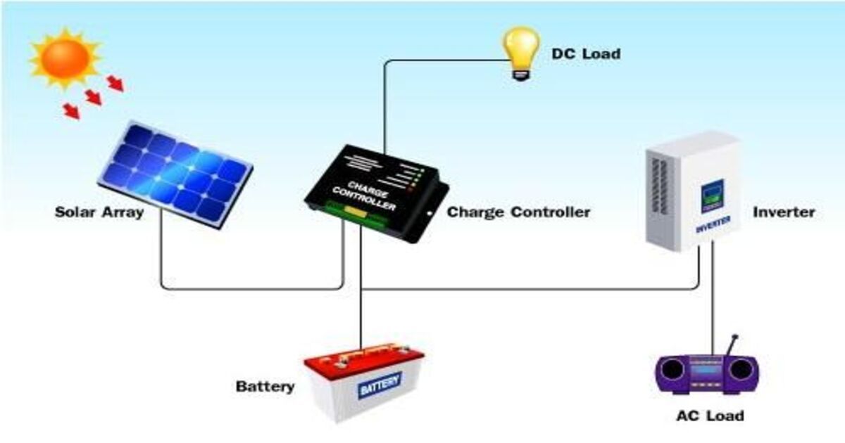
The article starts by listing the major components of a PV system. It then goes on to explain the design of each of these components. In the end, an easy and convenient method for designing a solar PV system is described.
Energy Demand Calculation is the first step of designing a PV system as it helps in calculating the rating and the power demand for which the PV system is to be designed. A system must be designed for maximum load demand. This increases the reliability of the system and ensures that the system operates even in peak load conditions. The energy demand of an appliance is calculated by multiplying the watt rating of the appliance with the duration for which the appliance operates. Hence the unit becomes watt-hour. The total energy demand of a system is calculated by adding the watt-hour rating of all the appliances. The total watt-hour rating of all the appliances of the system is multiplied by 1.3 to include the losses. As the system is designed for peak load conditions the cost of the system increases. But this ensures the reliability of the system. To reduce the cost of the system the reliability has to be compromised. Hence a selection between the two is essential while calculating the energy demand of a PV system.
For the design of an inverter, the input and output voltage and current have to be specified. The system load defines the output voltage of the inverter. The inverter should be able to handle the load current and battery current. The inverter power rating is specified based on the total connected load.
Usually, in residential systems, the inverter power rating is chosen to be twenty-five to thirty percent higher than the total connected load. The increase is taken to compensate for the losses in Inverter. For applications like motors, the inverter power rating is chosen approximately three times higher than the rating of the motor.
The size of the inverter is twenty-five percent higher than the total connected load. It is rated at 125% of the watts of the total connected load.
Let’s consider an example to understand how the sizing of the inverter is selected. Suppose the total connected load is 3000 watts. Then an inverter of size 3000 X 125/100= 3750 watts should be selected. Hence, for a connected load rating of 3000 watts, the inverter of power rating 3750 should be chosen.
The size of the PV module determines the output which it is going to produce. To calculate the size of the PV module, the total watt peak rating should be calculated. To calculate the total watt peak, divide the total watt-hour rating of the PV system ( obtained from the calculation of energy demand ) by the panel generation factor. The panel generation factor depends on the climate and the temperature of the site location. To calculate the number of PV modules required for a system, divide the total watt peak by the rated output of the selected panel in peak watts.
The number of PV modules obtained is the minimum number of models that can be used in a system.
By installing more PV modules the system performance will increase and it will also enhance the battery life. But if less number of PV modules are used than the minimum number of PV modules required in a system then the PV panel will not produce any output in cloudy conditions and the battery life will reduce. Thus, it is advisable to always install more PV modules than the minimum number.
For the design of the battery, the following three parameters are to be considered.
The batteries used for solar PV systems are deep-cycle batteries. Deep cycle batteries discharge at low energy levels, and they recharge and charge rapidly. The battery should be designed in such a way so that it is large enough to store sufficient energy which can be used during night, in monsoon season, and in cloudy weather conditions. The battery size is calculated by following the given steps.
The total watt-hour of all the appliances is calculated. An efficiency of 85% is considered. Hence the total rating of all the appliances is divided by 0.85. A depth of discharge of 60% is considered for deep-charge batteries. The result is divided by the depth of discharge of the battery. The obtained result is then divided by the nominal battery voltage. This results in the number of days of autonomy of the battery. By this calculation, the ampere-hour capacity of a deep charge battery can be calculated.
The maximum power extracted from a battery also indicates battery capacity. Battery capacity depends on the age and history of the battery, temperature, and the discharging and charging regimes of the battery. The unit of battery capacity is Ampere hours. Ampere hours are hours when the current equals the discharge rate of the battery.
Ampere hour = (Total watt-hour of all applications X number of days of autonomy) / ( 0.85 X 0.6 X Nominal battery voltage )
The rating of the charge controller is 125 % of the short circuit current of the PV panel. Usually, a safety factor of 1.25 is taken.
Rating of solar charge controller in amperes = Short-circuit current of PV × Safety factor.
Suppose a PV system of 5 PV modules each of 20 Amperes is to be designed. The rating of the solar charge controller required in this case will be 20 X 5 X 1.25 = 125 A
The cable design depends on the maximum current carrying capacity. The Voltage drop in a cable should be minimal and should not be more than 2 %. To reduce the voltage drop within the cable the resistive loss should also be minimal. As PV systems are installed outdoors to capture solar energy the cable should be strong enough to withstand different environmental conditions. If cables are undersized in design then it results in energy loss. If cables are designed oversized then it will increase the cost.
The cross-sectional area of the cable is calculated using the formula below.
A= [( rho X I X L ) / V ] X 2
Here, rho resistivity of the conducting material of the wire. Its unit is an ohm meter. L represents the length of the cable. V represents the maximum permissible voltage drop within the cable. I represent the Maximum current to be carried by the cable.
Using this formula the cable of optimum size can be calculated.
PV systems are mounted on durable and stable structures. These structures can support the system reliably and withstand hail, wind, and rainy conditions. The mounting structure also tilts the PV system by a fixed angle which is determined by the latitude of the location and the load requirement. The tilting of the PV array at a fixed angle also ensures maximum output from the system. Rack mounting is the most common method of mounting PV arrays. It is versatile, robust, and easy to install and construct. For ground-mounted PV arrays, tracking mechanisms are used to move the panel to follow the sun across the sky to obtain maximum output. On-axis trackers are used to track the sun from east to west. Two-axis tracker modules are allowed to directly point the module at the sun in one direction throughout the day. Thus, mounting systems are installed according to the location of the PV system to obtain the maximum output.
Installing a PV system requires different work like preparing the CAD layout, energy simulation for the future, and preparing different reports and quotations. With the help of ARKA 360, the process of installing a PV system is unified. All essential services required for the installation of PV systems are available in just one software. It streamlines the entire design process. This not only saves time but also helps in preparing better designs.
The article starts by talking about the major components of a solar PV system. Components like solar panels, inverters, batteries, solar charge controllers, wires/cables, and the load of a PV system are explained. The very first step in designing a PV system is the calculation of the load requirement. Hence the energy demand calculation is discussed first. Further, the design of the inverter, PV module, battery, and Solar charge controllers are explained. It is also equally important to mount the PV system on a stable structure so that maximum output is obtained and the system is reliable. Different types of mounting systems that are used to extract maximum output are listed. All this work results in a very lengthy process.
ARKA 360 software is designed to make this process simplified and it acts as a one-stop solution for the installation of PV systems.

