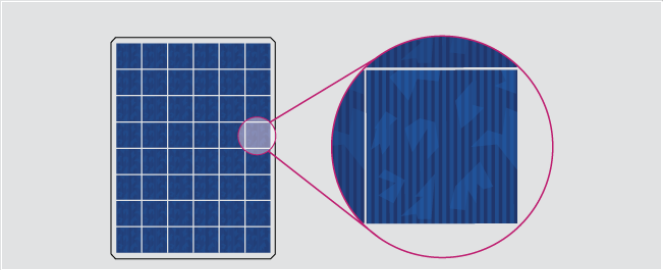
To understand the basics of photovoltaics, we must first come to the building block of solar panels which are known as solar cells and their types, interconnections and ratings as per industry standards. In photovoltaics, many cells combine to form a solar panel and many panels combine to form an array.
Typically, residential systems use panels made from 60 solar cells whereas commercial systems use panels made from 72 solar cells. As we increase the number of cells, the voltage and power generated also increases. They’re insulated and framed to be protected from harsh environmental conditions and also to protect the user from untoward accidents. So, in this article, you’ll be able to obtain a basic understanding of solar photovoltaics, types and important factors that need to be considered when investing in solar technology.
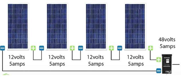
The basic ‘nerves’ of the solar module array which sends signals or currents to different parts of the system principally depends on the module circuits are designed in such a way that the multiple cells that make a module are connected to increase the power and voltage obtained from the device. The design is done under standard test conditions where maximum power is acquired at 0.5V at 25°C. Therefore, when it comes to circuit design of PV modules, there are 2 classifications which are:
Modules connected in series usually consist of wiring the positive terminal of one solar cell to the negative terminal of another solar cell such that voltage increases and current remain the same across the circuit.
💡
For more such amazing content, do follow our LinkedIn page. 👇
However, since wiring is involved, there’s a chance for mismatch losses to occur. These losses are caused by interconnection defects of solar cells or solar modules because of varying properties or conditions. For example, if a part of a solar cell or module is shaded, the overall power being generated will be lower than the expected system performance output because the power that’s being generated at the good side of the cell/module will be dissipated due to improper wiring. This, in turn, will lead to localized heating which may damage the cell or module irreversibly. Most of the PV modules are connected in series which leads to a higher chance of series wiring mismatch that occurs in the circuit. There are 2 types of series mismatches:
Open-circuit voltage mismatch: This is a mismatch that’s not significantly threatening to the module but its effects are pronounced when the overall power is being calculated. In series, current remains the same but the overall voltage is increased by adding voltages at various values of current.
Short-circuit current mismatch: A short circuit current mismatch has a drastic effect on the module because current passing through the solar cells is the same. The overall current depends on the ‘poor cell’ because it cannot exceed it. This leads to dissipation of power at the poor cell which can cause perpetual damage to the module

Modules connected in parallel involve connecting all the positive terminals together and all the negative terminals together in the module. This wiring increases the current flowing through the circuit and keeps the voltage same throughout.

Usually, in PV systems, we find a combination of series and parallel wiring. This is common in large systems used for residential or commercial purposes. The combination wiring is used for large PV arrays wherein a set of solar cells/modules connected in series is known as a ‘string’. Since a combination wiring design is used, there are chances for mismatch effects to occur at an array scale because of the series and parallel connections present in the circuit design.
These effects can significantly affect the entire array if by-pass diodes are not connected. By-pass diodes are connected in parallel. They help in reducing the effective resistance and are usually accompanied by another diode called a ‘blocking diode’ which prevents overloading in the module. They are wired in series.
Each string present in the array should be equipped with its own blocking diode because these diodes reduce mismatch losses that frequent in arrays having parallel connections by inhibiting the flow of current from parallel strings to strings of lower current. They prevent current from flowing into modules that are possibly shaded which if it did flow, can lead to overheating and solar cell damage

Fortunately, with current developments in loss management and encapsulation techniques, manufacturers can give a module lifetime guarantee for more than 20 years where for the first 10 years, the module will produce 90% of its total rated output and approximately 80% for the next 25 years which shows the robust nature of PV modules in the current market.
When we consider the current market for solar PV technologies, there is an expected to grow to USD 345 billion by 2020. The main reasons for this projected growth are because of increasing demand for energy, a noticeable concern for sustainable practices and the Government’s support for the same.
Solar panels made from crystalline silicon are expected to hold the majority of the market share because of their semiconductor properties and competitive costs in the market. Photovoltaic technology made from inorganic materials such as Silicon, CdTe, CIGS, Amorphous silicon, etc. are the major contenders because of their potential to achieve high efficiencies. The utility applications have the highest demand for PV market primarily in defence, space utility, military applications and in power plants.
The Asia-Pacific (APAC) region had the largest share in the PV market because of Governmental initiatives to shift towards the Renewability sector. Therefore, the production costs are low and often supported by Government subsidies. The major contributors from these regions are India, South Korea, Japan, China and Thailand

Since the market trend is expected to play a major role in solar panel production, it is essential to know the different types of panels that exist in the market.
💡
Looking for the Best Solar Design Software? With ARKA 360, easily manage your solar designs, and convert more customers with 3D models and financial reports.
There are mainly 5 types of solar panels that currently hold the market. They differ in terms of manufacturing processes, properties, cost and efficiencies and the panel type must be selected according to the installation type that is being considered. They are known as:


Amorphous Silicon Panels: Another commonly used thin-film technology is amorphous silicon which has been one of the most widely used thin-film technologies in the market ranging from powering remote facilities to even pocket calculators. This technology involves depositing a thin silicon layer on a substrate such as metal or glass which is layered in a p-i-n structure. Their major advantages are its sensitivity to light which aids in light absorption, heat resistance and flexibility which makes them less prone to panel breakage during its installation and transport. It can be manufactured in a variety of shapes and sizes and have low manufacturing costs making the technology more accessible. On the other hand, this technology has lower lifetimes than of monocrystalline or polycrystalline solar cells and its efficiency is only around 7%-9% because of an effect called as the Staebler-Wronski effect which degrades the performance of the panel during its initial exposure to sunlight leading to a decrease in the efficiency from around 10% to 7%


These steps are done to ensure the benefits offered by PERC technology are established during its operation

When considering solar panel and its installation, it is necessary to know the module ratings for the panel because that will determine the efficiency of rated output power generated from the panel. Some factors to consider are:
Apart from these factors, it is also necessary to consider the system sizing of the solar cells and arrays because it can significantly affect the energy yield as well as the cost of the investment into this technology.
The first thing that needs to be measured is the total kilowatt-hour use for the past 1 year. The peak sun hours for the proposed site must also be taken into consideration. Then to determine the system size, the following equation must be taken into consideration:
System size=Annual kWh x Annual PSH x Derate factor
Derate factor is the value of the unavoidable losses that a system encounters when converting the array’s DC into AC.
To size a string, we must do the following:
An example would be:
Given: Calculate number of modules that need to be configured in series
Solution:
1.1365 x 36 = 40.914
Since we’re calculating number of modules in cold temperatures, we should take just 14 modules.
The required wattage of modules can be calculated by:
Module watts needed = System size / Total number of modules
Hence, to size an array, apart from the above equations we need to consider the array length and width, module size and orientation, tilt angle (if required) and hardware requirements which shall be explained in another article
In conclusion, we can see that when it comes to understanding the basics of photovoltaics, there are multiple concepts we need to understand which have been briefly explained in this article. This article gave an overview of the wiring sequences that are most commonly used in solar panel connections followed by the mismatch losses that occur due to the complexity of these wiring practices. This article also followed the current market trends and how it’s expected to grow in the future due to the ever-increasing energy demands and the rise in concerns of sustainability. The different types of solar panels that dominate the world market have also been discussed followed by some factors and parameters that are important during the sizing of such PV systems for utility applications. From this time, it is important to contemplate the current circumstances under which the renewable energy sector is growing and how it is going to impact the future of the energy industry with a positive change!


